Like all the software Engineers we had this class called, Data bases where we learn about SQL, a little of UML, keys, diagrams, etc…
But now we have a concept in terms of design that is related with databases and is how to convert Classes to tables
So in previous blogs we explain about classes with UML, where we can find attributes of a class the kind of object etc… So now we have to convert this information in tables, so the first thing that we have to check is data attributes of a class. An attribute will map to zero or more columns in a relational database.
For example, a Student object may have an averageMark attribute that is needed within your application but isn’t saved to the database because it is calculated by the application. Because some attributes of an objects are objects in their own right, a Customer object has an Address object as an attribute – this really reflects an association between the two classes that would likely need to be mapped, and the attributes of the Address class itself will need to be mapped. The important thing is that this is a recursive definition: At some point the attribute will be mapped to zero or more columns.
We have some Mapping Terminology
Mapping (v). The act of determining how objects and their relationships are persisted in permanent data storage, in this case relational databases.
Mapping (n). The definition of how an
object’s property or a relationship is persisted in permanent storage.
Property. A data attribute, either implemented as a physical attribute such as the string firstName or as a virtual attribute implemented via an operation such as getTotal() which returns the total of an order.
Property mapping. A mapping that describes how to persist an object’s property.
Relationship mapping. A mapping that describes how to persist a relationship (association, aggregation, or composition) between two or more objects.
Let’s go again, I know maybe you are like common men it’s your third post about UML, but this is why I’m talking about UML, because this language has a lot of good things. In previous post we saw, things like history, how to use it, diagrams of sequence, classes and objects. Now let’s talk about state diagrams, package diagrams, GRASP and MVC.
In my class of software engineer we saw a lot of good things of UML but one of the most important things was state diagrams, because are really helpful.
A state diagram is used to represent conditions of the system or part of the system at finite in stance of time. It’s a behavioral diagram and it represents the behavior using finite state transitions. So if we take a look in the real world, we can see that is really easy to use.
We use it to state the events responsible for change in state (we do not show what processes cause those events).
We use it to model the dynamic behavior of the system .
To understand the reaction of objects/classes to internal or external stimuli.
This video will explain a lot better.
Diagram state are important but package diagrams too so, what does do a Package diagram?, is kind of structural diagram, shows the arrangement and organization of model elements in middle to large scale project.
Package diagram can show both structure and dependencies between sub-systems or modules, showing different views of a system, for example, as multi-layered (aka multi-tiered) application – multi-layered application model.
Photo by VisualParagdim
General Responsibility Assignment Software Patterns (or Principles), abbreviated GRASP, consist of guidelines for assigning responsibility to classes and objects in object-oriented design.
Well this part of UML I have to say that it’s a little complicated to me explain this topic, because a like it a lot and more because in my class we have a session with Kent Beck one of the pioneers of this topic. So I will try to explain a little about what I learn.
General Responsibility Assignment Software Patterns (or Principles), abbreviated GRASP, consist of guidelines for assigning responsibility to classes and objects in object-oriented design. It is not related to the SOLID design principle.
Creator: Decide who cam be creator based on the objects association and their interaction.
One example of Creator is a VideoStore, because has an aggregation association with Video, VideoStore is the container and the Video is the contained object.
Well later we have MVC (Model, View, Controller) maybe in this point if you are reading this, the topic will be sound familiar, because this is something very popular so lets go with this.
We have 3 parts of this
Model represents an object or JAVA POJO carrying data. It can also have logic to update controller if its data changes.
View – View represents the visualization of the data that model contains.
Controller – Controller acts on both model and view. It controls the data flow into model object and updates the view whenever data changes. It keeps view and model separate.
Implementation
We are going to create a Student object acting as a model .StudentView will be a view class which can print student details on console and StudentController is the controller class responsible to store data in Student object and update view StudentView accordingly.
Well I talked about UML in my previous posts, but now i can talk about a little deeper about this one. Like I told you in previous post, I like UML because is easy to understand, to learn and use. But let me tell you why.
Well let’s start with the sequence diagram of UML, is really easy to understand and use it, because is like a process that you have to follow, it’s the process literally you want to follow in your app, system, etc. . .
One example that I can tell you about it is a shopping car, the process of a purchase in a e-commerce can be in different ways, with different steps, but with UML you can follow a process like the next image.
Photo by Lucidchart
So let’s me explain a little this photo, we have a customer that is buying anything he can do a lot of things in the first step, like add item, delete item, display cart, purchase or get status, but later he pass to the next step where again he can do a lot of things , but with UML sequence it’s really easy to understand this process and when you have to code this the process will help you a lot.
In another hand, we have other two important things that we can do with UML.
Objects: In this part is really easy to describe or declare an object, because here you include objects and data values, the class of the object, in few words is a snapshot of what we want.
Class: Here is also really useful because a class show what the objects in your system consist and what are capable to do. In contrast, an Object Diagram shows how objects in your system are interacting with each other at some point in time
Photo by VisualParadigm
So in resume, UML have a lot of diagrams that working together can be a base for a system, that will help you to declare some steps, classes, objects, that at the time that your are coding will help you a lot.
For more information about UML I will let you here a few of links with more information if you want to learn more about the topic.
Well, It’s great how with this kind of teaching is really easy to organized your time and in the same time we learned a lot, because you have to write this blog, so you must to read something, understand it and explain it, so is really great this.
So let’s start with this reflection about what I learned this first partial, so i will divide in two parts each topic, first a little explanation about what it’s and later what I learned about this topics so let’s start.
Life Cycle
The software
development life cycle (SDLC) is a framework defining tasks performed at
each step in the software development process. SDLC is a structure
followed by a development team within the software organization.
It
consists of a detailed plan describing how to develop, maintain and
replace specific software. The life cycle defines a methodology for
improving the quality of software and the overall development process.
The software development life cycle is also known as the software development process.
Unified Software Process
Unified process (UP) is an architecture-centric, use-case driven,
iterative and incremental development process that leverages unified
modeling language and is compliant with the system process engineering
metamodel. Unified process can be applied to different software systems
with different levels of technical and managerial complexity across
various domains and organizational cultures.
UP is also referred to as the unified software development process.
Modeling Languages and Tools
Well in this topic I choose UML because I think it’s one of the most use it so let’s talk about this great Language Model:
First some of history, born in 1994 by Grady Booch, James Rumbaugh and Ivar Jacobson. The first version 1.0 of UML was released in January of 1997.
Some advantages of use UML are really greats just like:
Better time of development.
Modeling System (no just software) using OOP.
Is a Language that is used for humans and computers.
High reuse and cost minimization.Better time of development.
Design Patterns
Design Patterns provides a general reusable solution for this commons mistakes. The patterns typically show relationships and interactions between classes or objects. The idea is to speed up the development process by providing well tested, proven development/design paradigm. Design patterns are programming language independent strategies for solving a common problem. That means a design pattern represents an idea, not a particular implementation.
Sometimes we have a lot of problems when we design some projects, so that’s why the design patterns it’s a real option to solve this kind of problems, but why?
Design Patterns provides a general reusable solution for this commons mistakes. The patterns typically show relationships and interactions between classes or objects. The idea is to speed up the development process by providing well tested, proven development/design paradigm. Design patterns are programming language independent strategies for solving a common problem. That means a design pattern represents an idea, not a particular implementation. By using the design patterns you can make your code more flexible, reusable and maintainable.Design Patterns provides a general reusable solution for this commons mistakes.
Types of Design Patterns
There are mainly three types of design patterns:
Creational These design patterns are all about class instantiation or object creation. These patterns can be further categorized into Class-creational patterns and object-creational patterns. While class-creation patterns use inheritance effectively in the instantiation process, object-creation patterns use delegation effectively to get the job done. Creational design patterns are the Factory Method, Abstract Factory, Builder, Singleton, Object Pool, and Prototype.
Structural
These design patterns are about organizing different classes and objects
to form larger structures and provide new functionality.
Structural design patterns are Adapter, Bridge, Composite, Decorator, Facade, Flyweight, Private Class Data, and Proxy
Behavioral
Behavioral patterns are about identifying common communication patterns between objects and realize these patterns.
Behavioral patterns are Chain of responsibility, Command, Interpreter, Iterator, Mediator, Memento, Null Object, Observer, State, Strategy, Template method, Visitor
If you are interested to know more about this you can check this page and this book
E-sports is the sport of the future, billions of dollars of revenues and prestige, a lot of teams around the word and Mexico is a little behind of all this, but here in the Tecnologico of Monterrey campus Guadalajara, we have our new arena gaming for our representative teams of e-sports so we think about the problems that we have. So we look up the coach of the team of Borregos GDL Lol team.
Photo by Alejandra Sánchez y Carmen Huerta
After talking with Eder Lagos, who is in charge of the representative team of LoL in the Tec and also the new Arena.
He told us that now they are implementing a process to choose the best players of the Tec, promoting tryouts for the people who are interested. The problem is that no much people get noticed about the try outs, and maybe there are good players who are missing this opportunity, or maybe they don’t even know that there is a representative team of LoL.
So, the main problem is the communication with the players. With our app, the administrator will check the players stats and invite them to the try outs if they are good enough, depending of course on the ranking generated by the API.
Then we realize that here is a big opportunity to do something about this problem.
In the last years, the team Zaga Collegiate has been representing TEC Guadalajara on a university league, in which compete universities all around Mexico. Their goal is to keep growing and to represent Mexico on an international tournament. That is why they need to be as good as they can.
Photo by Zaga Gaming
Our idea is to make an API for League of Legends. This API will allow the administrators of the representative team in the University to scout and find the best players, in order to bring quality and internal competition to the Zaga Collegiate team. We think that there must be awesome players hidden in the shadows, that individually play even better than the players who are in the representative team.
Photo by Masharelli
The way to achieve this goal is by an internal ranking where only the students from the TEC can participate. This ranking is independent from the LoL ranking. The ranking will be based in the final score of the game (Win/Defeat), the KDA of the player (Kills+Assists/Deaths), LoL ranking from the opponents (if the opponent is ranked Gold, it will give more points than a player ranked in Silver) and the grade obtained at the end of each game.
We will combine this information to generate a formula to determine how many points the player will win or lose on the TEC ranking. All the players information will be divided in the LoL positions: Mid laner, Top laner, Jungler, Support and AD Carry. All this information will be available for the coach and the administrators of the representative team, so they can invite or investigate more in detail a specific player.
Photo by League Of Legends
The users can also create a league where they can invite friends and prove who is the best of the group. The idea is to help TEC players to develop their skill on the game and to have a good time with their friends.
Lets talk about our stakeholders:
Normal player: A student of the Tec that plays League of Legends as a hobby. This is the user of the API. His statistics will be saved on the API.
Representative team player: A student of the Tec that is a member of the Zaga Collegiate representative team. This is the user of the API. His statistics will be saved on the API.
Administrator: He is in charge of analysing the performance of the best players in the API. He has statistics of all the players at hand.
Client: Our client is the person in charge of the representative team in the Tec. He is the most interested part on the project.
Photo by EALDE
Our requirements give for our stakeholders
Normal player: Get an app where I can compete with all the other players in the Tec, in order to have the opportunity to be in the representative team. At the same time, rank my friends in customized leagues between us.
Representative team player: Get an app where I can prove that I am the best player in the Tec on my position. Generate internal competence. Rank with my friends to help them being better. Check players which are in the top of the ranking and see their stats.
Administrator: Get an app where I can see the stats of all the students who play LoL in the Tec. The purpose is to generate a giant scouting app, and the most important thing for me is to have an easy way to contact them if needed. Those people who I am interested in will be invited to the try outs of the representative team.
Client: Get my campus representative team as competitive as they can. Get the best players in each position representing the Tec.
Well, just to start let me tell you why I pick UML. I learned about Modeling languages in my university Tecnologico de Monterrey,
I’m software Engineer so i have a lot of classes about modeling software i think like 3, but in my first class Software Engineer, I met a lot of Modeling Languages and y fell in love of UML.
But, Why?. Simple UML is easy to learn, to do and to understand, so let me tell you a few things about why I prefer UML.
First some of history, born in 1994 by Grady Booch, James Rumbaugh and Ivar Jacobson. The first version 1.0 of UML was released in January of 1997.
So, you can see that is really intuitive, friendly and easy to do, here is a simple system of a E-commerce process of shop something.
Now we can see a tool for do it this kind of charts and is papyrus UML, in this case I recommend this program or plugin for programmers, because you can use it in eclipse at the same time you are programming and is really easy to use, here you can see all the symbols and arrows, that you have to use, you can create a lot of charts and save it.
We can have it specify situations and papyrus had this kind of charts.
A use case is a software and system engineering term that describes how a user uses a system to accomplish a particular goal. A use case acts as a software modeling technique that defines the features to be implemented and the resolution of any errors that may be encountered.
Photo by Wikipedia
Use cases define interactions between external actors and the system
to attain particular goals. There are three basic elements that make up a
use case:
Actors: Actors are the type of users that interact with the system.
System: Use cases capture functional requirements that specify the intended behavior of the system.
Goals: Use cases are typically initiated by a user to fulfill goals describing the activities and variants involved in attaining the goal.
For each category of users, create a user profile. This includes all roles played by the users relevant to the system.
Identify significant goals associated with each role to support the
system. The system’s value proposition identifies the significant role.
Create use cases for every goal associated with a use case template
and maintain the same abstraction level throughout the use case. Higher
level use case steps are treated as goals for the lower level.
Unified Process or better know it like UP is an architecture-centric, use-case driven, iterative an incremental development process that leverages unified modeling language and is compliant with the system process engineering meta-model.
Photo by Wikipedia
Unified process can be applied to different software systems with different levels of technical and managerial complexity across various domains and organizational cultures.
Unified process is based on the enlargement and refinement of a system through multiple iterations, with cyclic feedback and adaptation.
This system is developed incrementally over time, iteration by iteration, and thu this approach is also known as iterative and incremental software development. This system spread over four phases where each phace consist of one or more iterations.
Inception—the first and the shortest phase in the project. It is used to prepare basis for the project, including preparation of business case, establishing project scope and setting boundaries, outlining key requirements, and possible architecture solution together with design tradeoffs, identifying risks, and development of initial project plan—schedule with main milestones and cost estimates. If the inception phase lasts for too long, it is like an indicator stating that the project vision and goals are not clear to the stakeholders. With no clear goals and vision the project most likely is doomed to fail. At this scenario it is better to take a pause at the very beginning of the project to refine the vision and goals. Otherwise it could lead to unnecessary make-overs and schedule delays in further phases.
Elaboration—during this phase the project team is expected to capture a majority of system’s requirements (e.g., in the form of use cases), to perform identified risk analysis and make a plan of risk management to reduce or eliminate their impact on final schedule and product, to establish design and architecture (e.g., using basic class diagrams, package diagrams, and deployment diagrams), to create a plan (schedule, cost estimates, and achievable milestones) for the next (construction) phase.
Construction—the longest and largest phase within Unified Process. During this phase, the design of the system is finalized and refined and the system is built using the basis created during elaboration phase. The construction phase is divided into multiple iterations, for each iteration to result in an executable release of the system. The final iteration of construction phase releases fully completed system which is to be deployed during transition phase, and
Transition—the final project phase which delivers the new system to its end-users. Transition phase includes also data migration from legacy systems and user trainings.
If you want know more about this, you can take a look at this links:
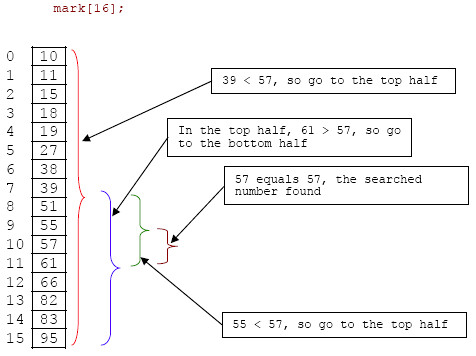
In this kind of games, we use binary search, The binary search consist in find the position of a target value within a sorted array. Binary search compares the target value to the middle element of the array. If they are not equal, the half in which the target cannot lie is eliminated and the search continues on the remaining half, again taking the middle element to compare to the target value, and repeating this until the target value is found. If the search ends with the remaining half being empty, the target is not in the array.
Well in this game we use the simple case of binary search like a game, because we are trying to guess one number and we only use binary search, so we apply some data structure, with algorithms and we have this great game.